How to Reduce Material Waste in Precision Die Cutting
Waste in precision die cutting is not simply the visible skeleton left after parts are removed. It includes edge trim, setup length, splices, leaders, inspection samples, rejected parts, unusable roll remnants, and functional material trapped in a construction that is wider or more complex than the part requires. Because these losses arise at different stages, a lower material price does not necessarily create a lower cost per accepted component.
A useful reduction program starts with a material balance: purchased usable area enters the process; accepted parts, unavoidable process allowances, recoverable remnants, and losses must account for the same area. That calculation prevents a dense-looking CAD nest from being mistaken for a stable production yield.
Design Precision Die-Cut Parts for Stable Nesting
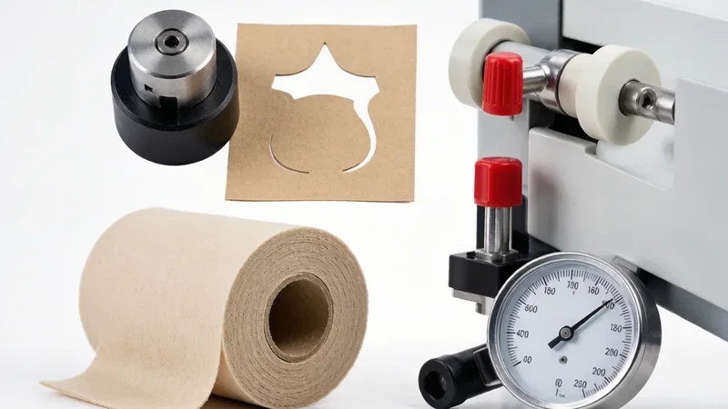
Part area alone does not determine utilization. A projecting tab can prevent alternate rotation; a large corner radius can force wider pitch; and several small internal cutouts can create a weak matrix that breaks during stripping. The engineering target is therefore the smallest repeat that still leaves enough matrix strength to travel through the press.
Classify every feature as functional, handling-related, or cosmetic before tooling. Functional sealing lands, locating holes, insulation clearances, and adhesive contact zones should be protected. A nonfunctional outside corner, decorative notch, or oversized pull tab may be adjusted if it unlocks another lane or eliminates an unstable waste bridge. When two mirrored parts use the same material and orientation, alternating them can improve yield without changing either component.
Tolerance allocation matters for the same reason. Tight limits on noncritical outer edges turn natural web wander, foam recovery, or liner stretch into rejection. If you are defining those limits, compare how material behavior and inspection conditions set realistic die-cutting tolerances before releasing the drawing.
Match Precision Die Cutting Layouts to Real Roll Width
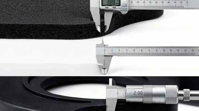
A layout should be calculated against the usable slit width, not the nominal master-roll width. Edge damage, slitting allowance, web guiding, printing registration, and lamination alignment all consume width. Dividing nominal width by part width can consequently predict a lane that cannot run.
Evaluate at least three orientations and record the constraint that eliminates each rejected option. Rotation may be prohibited by foam cell direction, film machine direction, graphite thermal anisotropy, brushed surface appearance, printed graphics, or the unwind orientation required by automated placement. A denser orientation is invalid when it changes performance or forces manual assembly.
Order volume also changes the answer. A wider web may support more lanes, but a short release may leave several lanes under-consumed and create obsolete finished stock. For specialty materials, compare the value of the unused edge strip with the setup cost of a narrower slit. This is one reason the economic result must be reviewed alongside the tooling, setup, yield, and release-volume drivers behind total die-cutting cost.
Protect Matrix Strength During High-Speed Precision Die Cutting

Theoretical utilization rises as the gap between parts shrinks, but net output can fall abruptly when the waste matrix loses continuity. Sharp re-entrant corners concentrate tension. Narrow adhesive bridges elongate and string. Small slugs remain on the liner, while soft foam pieces can lift with the matrix if release force exceeds their adhesion to the carrier.
Validate the nest at production speed and after the tool reaches normal operating temperature. Record web breaks, manual interventions, residual slugs, adhesive buildup, and accepted pieces per hour. If a tighter pitch saves 2% of material but adds repeated stops or contamination risk, the layout has transferred waste into downtime and rejection rather than removing it.
Tool wear must be included in that trial. A marginal stripping window may look acceptable with a fresh edge and deteriorate after a longer run. Practical acceptance should cover the planned maintenance interval, not only the first clean samples.
Reduce Waste Across Multilayer Die-Cut Constructions
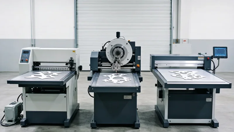
In a laminated part, the most expensive layer should not automatically cover the largest outline. A thermal pad may be required only over a heat source; conductive foil may need to bridge two grounding points; adhesive may only be needed in mounting zones. Island placement or selective lamination can reduce high-value material consumption while the carrier liner preserves handling.
The tradeoff is additional placement tolerance, lamination setup, and inspection. Calculate savings after including the extra conversion steps and the scrap created during registration. Selective lamination is strongest when the saved layer is costly, the functional island is substantially smaller than the carrier, and the registration window is compatible with material stretch and machine control.
Liner reduction requires similar discipline. A thinner liner uses less material but may curl, tear during stripping, or fail in an automatic dispenser. For pressure-sensitive constructions, review available tape and liner options suited to the required bonding and release behavior rather than choosing liner thickness in isolation.
Measure Total Yield for Precision Die Cutting Services
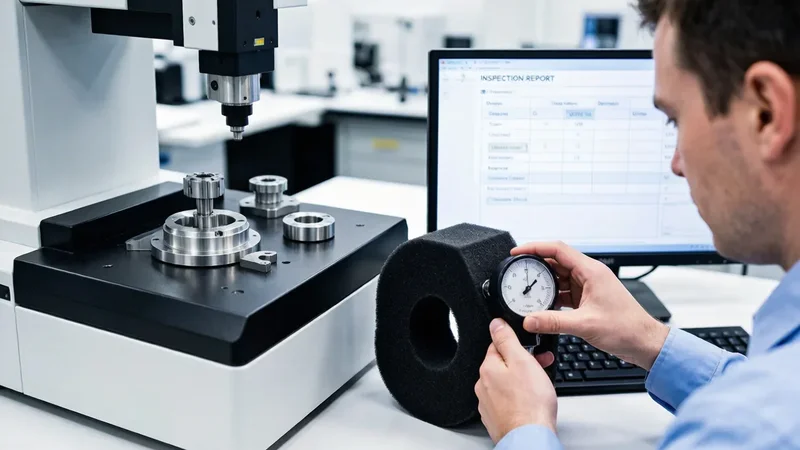
Use two complementary measures. Material utilization compares the net functional area of accepted parts with the usable material issued. First-pass yield compares accepted pieces produced without rework with total pieces made. High utilization with poor first-pass yield signals an unstable layout; high first-pass yield with low utilization points to geometry, pitch, or web-width opportunity.
For each lot, record issued length and usable width, edge trim, setup and splice length, matrix weight or calculated area, inspection samples, rejected quantity, accepted output, and any reusable remnant. Compare estimated consumption with actual consumption after several repeat lots. The variance identifies hidden losses that a quotation assumption cannot reveal.
Set an action threshold rather than demanding a perfect percentage. A repeated variance above the agreed band should trigger a review of nesting, tool condition, web tension, roll planning, or defect pareto. This converts waste reduction from a one-time drawing exercise into measurable process control.
FAQ About Precision Die-Cutting Material Waste

What yield data should a buyer request with a quotation?
Ask for assumed usable web width, lanes, pitch, setup allowance, expected rejection, and whether the quoted yield includes edge trim and leaders. A single utilization percentage is not comparable unless its boundary is defined.
When is a family tool a poor waste-reduction choice?
It is risky when component demand ratios vary widely. Production then creates excess inventory of the slower-moving part. Use a family layout only when material, revision timing, quality requirements, and consumption ratios remain compatible.
Should unused specialty material remain with the converter?
It can, provided ownership, storage conditions, remaining shelf life, traceability, and disposition after a design change are written into the purchase agreement. Otherwise the apparent saving may become obsolete inventory.
Can recycled content be substituted to reduce environmental impact?
Only after verifying thickness stability, adhesion, dielectric or thermal performance, cleanliness, aging, and regulatory documentation. Waste prevention and material substitution are separate engineering decisions.
Build a Yield Plan for Your Precision Die-Cut Component
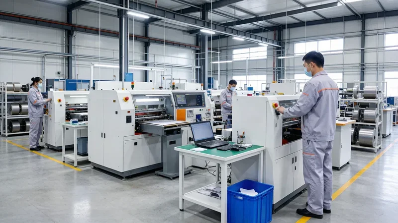
Send the controlled drawing, material construction, annual demand, release quantity, functional orientation, and delivery format. Xinyusheng can compare practical nests, usable roll widths, stripping margins, selective lamination, and lot-level measurement before production tooling is committed.
Table of Contents
Related news
Company News
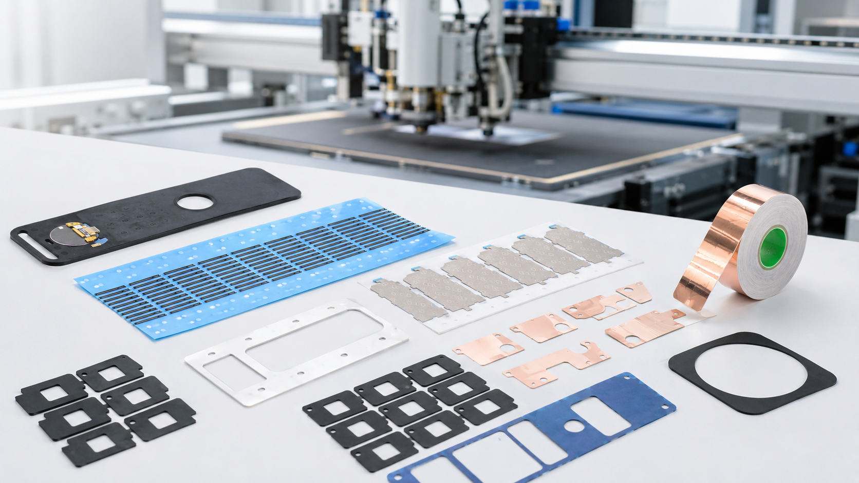
What Is Custom Precision Die Cutting? What Types of Custom Functional Components Is Xinyusheng Suitable For?
May 14,2026
Discover More
Company News
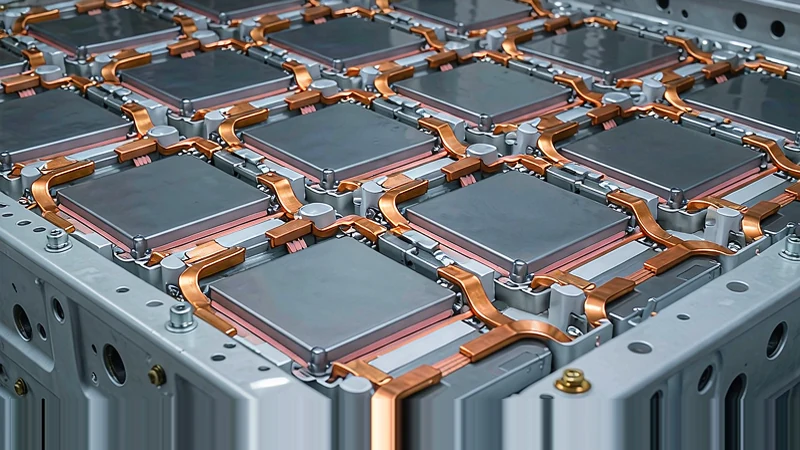
How Are Die Cut Materials Used in Automotive Electronics?
August 29,2026
Discover More
Company News
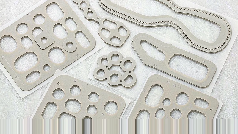
What Types of Thermal Interface Materials Can Be Die Cut?
August 29,2026
Discover More
