How Precision Die-Cut Tapes and Foams Improve Product Assembly
A tape or foam part does not improve assembly merely because its outline was die cut. The improvement comes when the component controls adhesive quantity, compression, orientation, liner removal, placement and delivery in a way that removes decisions from the workstation. If those elements are ignored, a precise profile can still be slow to apply or unreliable in service.
The most useful design question is therefore not “Can this material be cut?” but “Which sources of assembly variation must the converted part eliminate?” That answer links the material stack to the operator, fixture or placement machine that will handle it.
Control Bond-Line Geometry with Precision Die-Cut Adhesive Tape
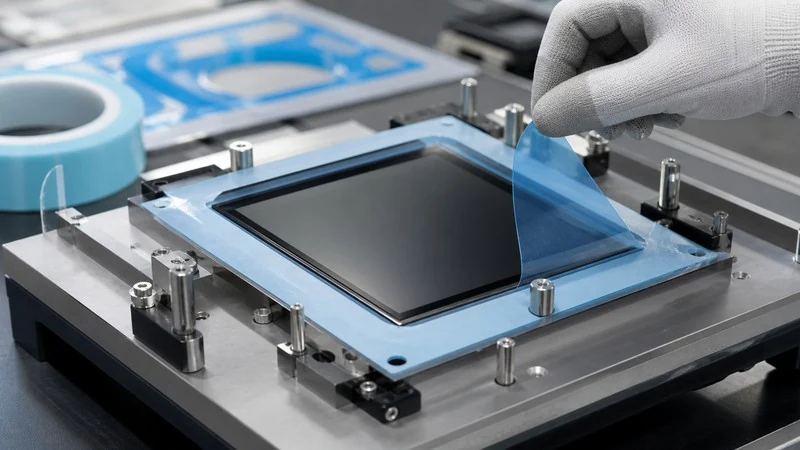
Liquid adhesive depends on dispense volume, bead position, wet-out, cure and squeeze-out. A die-cut pressure-sensitive adhesive establishes the bonded area and nominal thickness before it reaches the line. Frames can keep adhesive away from optical windows, vents and connector openings, while local reliefs prevent trapped air or interference with moving features.
Geometry cannot compensate for the wrong adhesive chemistry. Acrylic systems commonly support aging and environmental resistance; rubber-based systems can provide rapid initial tack; silicone adhesives may suit heat or low-surface-energy challenges. Final selection must consider substrate energy, surface texture, contamination, temperature, load direction, dwell time and whether clean removal is required.
A bond should also be validated after realistic application pressure and dwell. Initial tack is not the same as long-term holding power. When edge flow is a concern, review the material, pressure, storage and geometry conditions that cause die-cut adhesive ooze before approving narrow adhesive lands.
Engineer Precision Die-Cut Foam Around Compression

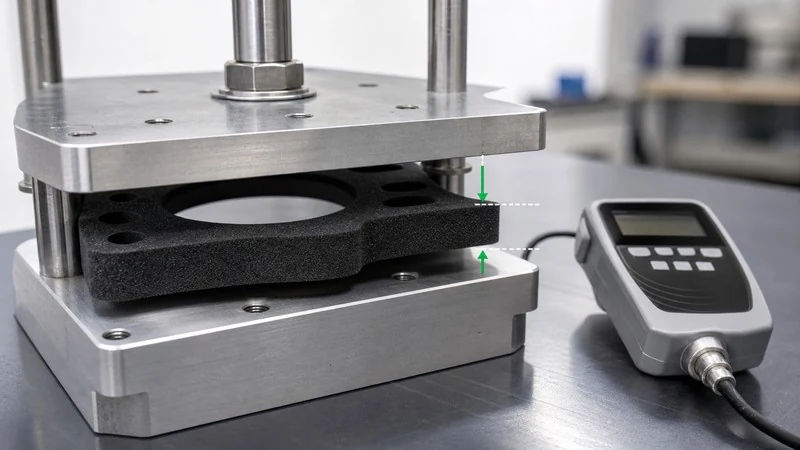
Foam can seal, cushion, damp vibration, control spacing and accommodate housing variation, but every function depends on its force-deflection behavior. A nominally thicker gasket is not automatically safer. Too little compression leaves a leak path; too much can increase closing force, distort a housing or accelerate permanent set.
Calculate the minimum and maximum installed compression from the complete tolerance stack: housing gap, foam thickness variation, adhesive thickness and component flatness. Then compare both limits with the material’s compression-force-deflection and compression-set behavior at the expected temperature. The seal must retain contact after dwell and aging, not only during the first assembly.
Cut geometry affects the result. Narrow walls buckle or relax differently from wide pads, sharp internal corners concentrate strain, and unsupported openings can distort during waste removal. Xinyusheng’s foam material options can be reviewed against sealing, cushioning and recovery requirements before the profile is frozen.
Design Liner Features for Repeatable Manual Assembly
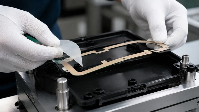
The liner is an assembly tool, not disposable packaging. A finger lift gives the operator a non-adhesive grip; a split liner can expose one locating zone before the remaining bond area; and an extended carrier can keep a flexible frame dimensionally stable until it reaches the fixture.
Place the liner split away from critical sealing lands and avoid a peel direction that stretches a narrow feature. The tab must be large enough for gloves when gloves are used, yet not so large that it consumes unnecessary material or interferes with adjacent parts. Release force should be high enough to retain the part during transport and low enough to prevent distortion during peel.
Validate the sequence at the real workstation. Record time to identify orientation, start the liner, place the part, remove the remaining carrier and apply pressure. Also record touched adhesive, folded tabs, dropped parts and rework. These observations often reveal more than a simple cycle-time average.
Prepare Precision Die-Cut Component Parts for Automation
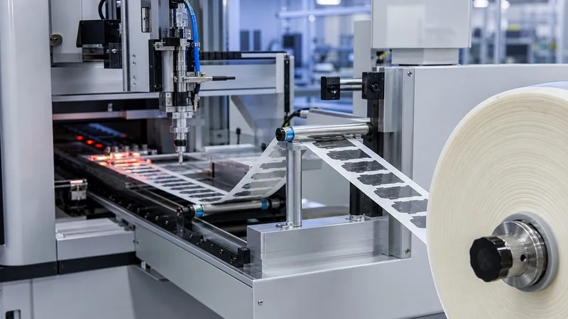
Automation requires a controlled system of pitch, unwind direction, orientation, liner stiffness, release force and pickup geometry. A part that is easy to remove by hand may curl, double-feed or remain on the liner when dispensed at speed. Very small flexible parts may need a temporary carrier or a larger sacrificial pickup zone.
Specify core diameter, maximum roll diameter, leader and trailer length, splice rules, winding tension and the part’s leading edge. Test enough consecutive parts to expose pitch drift, static, liner curl, cavity differences and adhesive buildup. A short run of selected samples does not demonstrate stable feeding.
When moving from prototypes to roll production, use the specification checklist for liner, orientation, inspection and delivery requirements so the automation assumptions become controlled purchasing data.
Validate Tape and Foam Performance on Real Surfaces
Published adhesion values are normally produced on prepared reference panels. Production surfaces may be textured plastic, powder-coated metal, coated glass or molded parts carrying release-agent residue. Curvature and continuous peel stress can lift an edge that performs well on a flat laboratory coupon.
Reproduce the intended cleaning method, application pressure, dwell, temperature, humidity, fluids and mechanical load. For foam seals, test the gasket inside the assembled joint and inspect retention after heat aging or cycling. For tape, evaluate the relevant failure mode—edge lift, shear creep, peel or substrate damage—rather than relying on one peel number.
ASTM D3330/D3330M offers recognized peel-test configurations for pressure-sensitive tape and release liners, but backing stiffness and elongation influence the measured response. Use the method for controlled comparison while keeping the actual product assembly as the final functional test.
FAQ About Precision Die-Cut Tapes and Foams
How many parts are needed for an assembly-line trial?
Use enough consecutive parts to represent normal handling, at least one material splice or roll transition where relevant, and the expected range of operators or machine cycles. The number should be based on the failure modes being observed, not a generic sample count.
Can one liner work for manual assembly and automation?
Sometimes, but manual peel preference may conflict with dispenser stiffness, curl and release requirements. Confirm both processes before committing to a shared construction.
Should a foam gasket be inspected in its free state?
Free-state dimensions are useful for incoming control, but sealing performance must be evaluated at the installed gap after the intended dwell and environmental exposure.
When is a kit sheet better than individual rolls?
A kit sheet is useful when one workstation consumes several different parts in a fixed ratio and visual completeness matters. Separate rolls are generally better when consumption rates differ or automation feeds each part independently.
Develop an Assembly-Ready Tape or Foam Part
Share the substrates, environment, drawing, gap and compression range, application sequence, production volume and delivery equipment. Xinyusheng can connect adhesive or foam behavior with geometry, liner design, inspection and packaging before tooling is released.
Table of Contents
Related news
Company News
What Is Custom Precision Die Cutting? What Types of Custom Functional Components Is Xinyusheng Suitable For?
May 14,2026
Discover More
Company News
How Are Die Cut Materials Used in Automotive Electronics?
August 29,2026
Discover More
Company News
What Types of Thermal Interface Materials Can Be Die Cut?
August 29,2026
Discover More
