How Material Type Affects Precision Die-Cutting Tolerances
A tolerance belongs to a material-process-measurement system, not to a machine by itself. PET can remain dimensionally stable as it crosses the tool, while silicone foam compresses, rubber recovers, pressure-sensitive adhesive flows, and graphite can fracture. Applying one “high-precision” number to all of them hides the physical mechanism that controls the finished part.
| Material family | Dominant dimensional risk | Control that matters most |
|---|---|---|
| PET / polyimide film | Web tension, thermal movement, static | Stable tension and datum-based optical inspection |
| Pressure-sensitive tape | Adhesive flow, liner stretch, tool buildup | Qualified liner, temperature and maintenance window |
| Foam / rubber | Compression, recovery, hardness variation | Conditioning time and low-force measurement |
| Foil / graphite | Burr, curl, cracking and handling damage | Tool condition, support liner and edge criteria |
| Thermal pad / laminate | Thickness variation and layer registration | Functional coverage plus layer-specific inspection |
Set Precision Die-Cutting Tolerances from Material Behavior
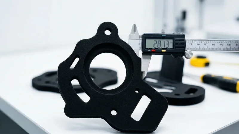
Start by identifying whether the material primarily stretches, compresses, flows, springs back or fractures. That mechanism determines where variation appears. Web stretch changes pitch and feature position along the machine direction. Compression and recovery change the apparent profile after cutting. Adhesive flow changes edges over time, while brittle sheet damage may not change the nominal dimension but still makes the part unacceptable.
Separate profile tolerance, feature position, layer registration, cut depth and thickness. They are different outputs with different causes. A multilayer part may hold its outside profile while the adhesive island shifts relative to the film. A kiss-cut tape may meet profile dimensions yet fail because the liner is scored too deeply for automated dispensing.
If a drawing uses one aggressive limit everywhere, first classify dimensions as critical, important or reference. Functional locating holes, seal widths and electrical clearances deserve process capability evidence; nonfunctional carrier edges should not consume the same inspection and rejection budget.
Control High-Precision Die Cutting of PET and Polyimide Film
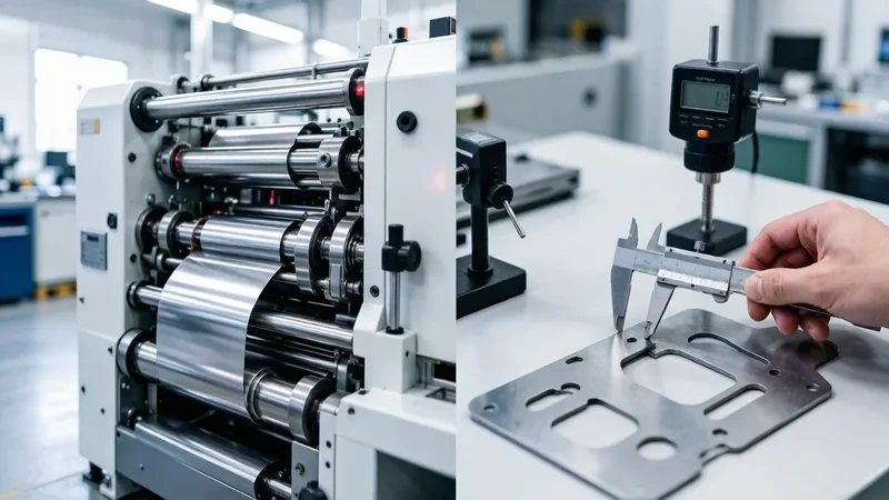
PET and polyimide are relatively stable and support clean features, but thin webs can wrinkle, telescope or drift when tension changes. Heat from lamination, curing or long production runs can alter pitch. Static can hold a light part to the tool or pull it out of its intended packaging position.
Measure film parts from a stable datum rather than chaining dimensions between flexible outside edges. For roll-fed components, sample by lane and by time because cross-web alignment and machine-direction pitch have different error signatures. A capability study should include normal running speed and warmed equipment, not only first pieces produced slowly.
When insulation function is critical, dimensional acceptance should be paired with edge integrity, contamination and minimum dielectric coverage. Review available insulation-film constructions for the required dielectric, thermal and handling conditions before assigning the final tolerance.
Account for Adhesive and Liner Movement in Precision Die Cutting
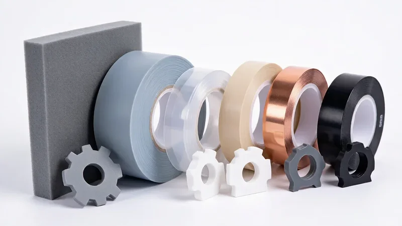
Pressure-sensitive adhesive is viscoelastic. Cutting pressure, temperature and dwell can move adhesive toward an edge; repeated contact leaves buildup that changes cutting conditions. The release liner carries the construction through lamination, cutting and stripping, so its elongation, stiffness, thickness and release force influence registration even though it is not part of the final assembly.
Define the measurement interval after cutting. An edge measured immediately may not match the same edge after storage under winding pressure. For narrow frames, include an edge-quality criterion and storage orientation. For kiss-cut parts, validate both functional-layer separation and residual liner strength across the tool-maintenance interval.
Adhesive movement is also a service risk. Use the adhesive-ooze failure analysis to evaluate temperature, pressure, geometry and storage when the allowed edge zone is small.
Measure Foam and Rubber Precision Die-Cut Parts Correctly

Soft materials can be distorted by the inspection method itself. Caliper force changes thickness; unsupported profiles sag; and freshly cut foam may recover for minutes or hours. A numerical tolerance without conditioning time, support surface and measurement pressure cannot be reproduced reliably between supplier and customer.
Define hardness or density range, nominal thickness, conditioning environment and the time between cutting and measurement. Where fit depends on a hole or slot, use a fixture or noncontact system that references a stable datum. Do not infer process instability from measurements made with uncontrolled compression.
Geometry sets another boundary. Small holes, narrow walls and sharp inside corners may tear during stripping even when the tool can reach the nominal position. The tolerance decision must therefore include minimum feature robustness and expected production speed—not only a drawing calculation.
Inspect Foil, Graphite and Thermal Die-Cut Components by Function
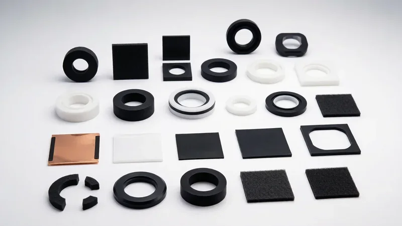
Copper and aluminum foil can hold accurate outlines yet develop burrs, curl or creases. Graphite may crack or flake at narrow features. Silicone thermal pads compress and can vary in thickness, so the dimension that matters most may be coverage of the heat source and resulting bond-line thickness rather than an isolated free-state edge.
Add functional criteria alongside dimensions: maximum burr where electrical clearance is limited, minimum conductive overlap at a grounding point, permitted surface damage, and minimum thermal coverage after assembly. A support liner can protect flatness and improve handling, but its removal must not fracture the part or disturb registration.
For multilayer thermal components, report outside profile and layer-to-layer registration separately. Accumulating them into a single tolerance prevents root-cause analysis and can drive unnecessary rejection.
Separate Incoming Material Variation from Cutting Variation
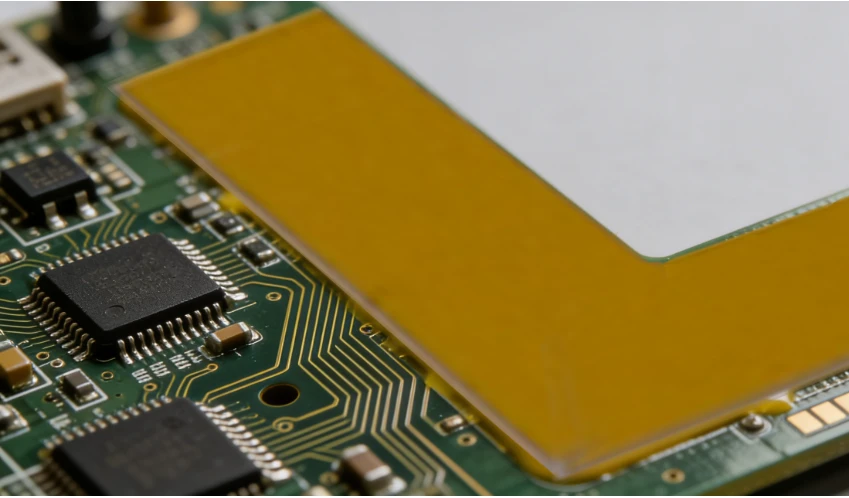
When a dimension drifts, changing the die is not always the correct response. Incoming rolls can vary in thickness, hardness, coating weight, width or liner release. Compare dimensional data by material lot, lane, cavity, time, temperature and tool-maintenance event. A change that follows the material lot suggests a different action from a change isolated to one cavity.
Confirm that measurement variation is small relative to the tolerance. A gauge repeatability and reproducibility study can expose operator, fixture and instrument effects. Capability indices calculated from selected samples or mixed measurement conditions create false confidence; use stable production data from the actual material stack.
For a broader drawing review, compare tolerance allocation, process capability and inspection methods for precision die-cut parts before final approval.
FAQ About Material-Specific Die-Cutting Tolerance

Can two brands of the same nominal foam share one tolerance?
Only after comparing thickness variation, hardness, cell structure, recovery and liner behavior. Nominal material labels do not guarantee equivalent conversion response.
Should tool compensation be included on the customer drawing?
No. The drawing should state the required finished geometry. Tool compensation is a controlled manufacturing decision validated with the actual material and process.
When should layer registration be measured?
Measure it after all laminating and cutting steps that can shift the layers, using agreed datums and conditioning. Measuring an intermediate laminate cannot prove final-part registration.
Is a tighter tolerance always more expensive?
It usually adds control, inspection or rejection cost, but the effect depends on material stability and feature function. Tightening only critical dimensions is more economical than applying one limit globally.
Validate Tolerance with Your Actual Material Stack
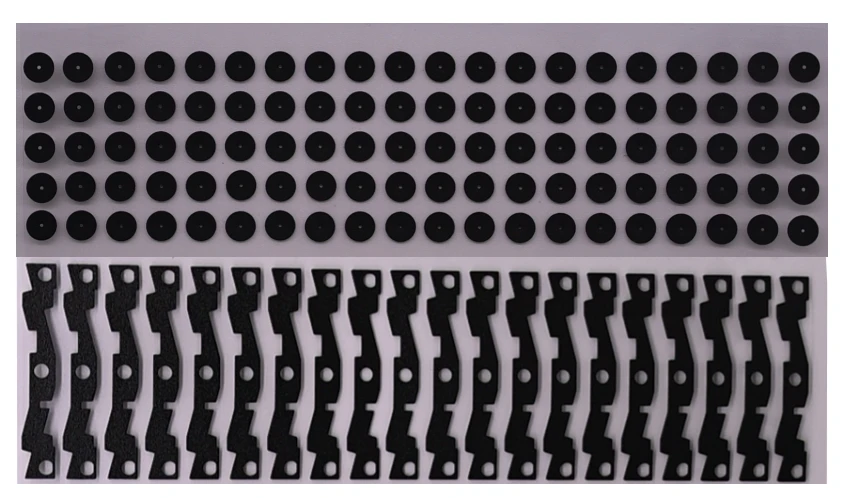
Send the material grade, thickness, adhesive and liner construction, critical datums, production volume and intended measurement method. Xinyusheng can evaluate the conversion route and validate a defensible tolerance using first articles followed by production-speed samples.
Table of Contents
Related news
Company News
What Is Custom Precision Die Cutting? What Types of Custom Functional Components Is Xinyusheng Suitable For?
May 14,2026
Discover More
Company News
How Are Die Cut Materials Used in Automotive Electronics?
August 29,2026
Discover More
Company News
What Types of Thermal Interface Materials Can Be Die Cut?
August 29,2026
Discover More
