Precision Die Cutting Tolerances: Materials, Thickness and Inspection
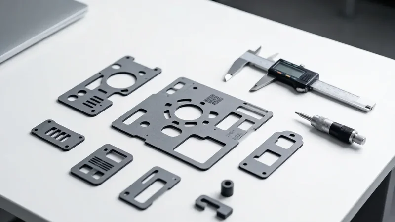
Precision die cutting tolerances determine whether a converted component can fit correctly, align with other parts, maintain sealing performance, or move smoothly through automated assembly. However, achievable tolerance is not defined by the cutting machine alone. It is the result of material behavior, thickness, part geometry, tooling, web handling, lamination, environmental conditions, and inspection methods.
For this reason, there is no single tolerance value that applies to every precision die cut part. A thin PET insulation film, a thick foam gasket, a conductive fabric component, and a multi-layer adhesive assembly may require completely different tolerance strategies.
The most reliable approach is to review the drawing, identify critical dimensions, evaluate the material structure, produce samples, and verify the results before mass production.
What Is a Precision Die Cutting Tolerance?
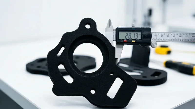
A die cutting tolerance is the acceptable variation between the nominal dimension shown on a drawing and the actual measured dimension of the finished part.
For example, when a drawing specifies a dimension with a stated tolerance, the completed component must remain within the permitted upper and lower limits. Whether that range is practical depends on the material and manufacturing process.
Several types of tolerances may be involved in custom precision die cutting:
Dimensional tolerance: Overall length, width, diameter, or profile size.
Positional tolerance: The location of a hole, slot, cutout, or feature relative to a datum.
Registration tolerance: Alignment between multiple material layers, printed graphics, adhesive zones, or liner features.
Thickness tolerance: Variation in the total thickness of a single material or laminated assembly.
Kiss-cut tolerance: Control of the cutting depth so the part is cut without damaging the release liner.
Edge or frame tolerance: Control of narrow walls, borders, and the distance between adjacent features.
These tolerances do not always need to be equally strict. Dimensions that control sealing, electrical contact, thermal contact, or automated placement normally require closer attention than non-functional outer edges.
Why Machine Accuracy Is Not the Same as Part Tolerance?
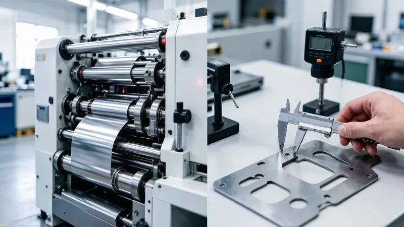
Machine repeatability is only one part of the final result. A die cutting system may position material accurately, but the finished component can still change after cutting because flexible materials stretch, compress, recover, shrink, or move during processing.
The final tolerance of a precision die cut component is influenced by the combined variation from:
Raw material + lamination + web feeding + tooling + cutting pressure + waste removal + measurement
A machine specification therefore should not be used as a guaranteed finished-part tolerance without considering the complete process.
For example, a soft foam may compress as the cutting tool enters the material. After the tool is removed, the foam can recover unevenly and change the measured profile. A thin adhesive film may stretch slightly during feeding and then contract after it is released from web tension. A multi-layer assembly may be dimensionally stable in each individual layer but still show registration error after lamination.
This is why experienced precision die cutting services evaluate the complete material structure rather than relying only on equipment specifications.
Main Factors That Affect Precision Die Cutting Tolerances
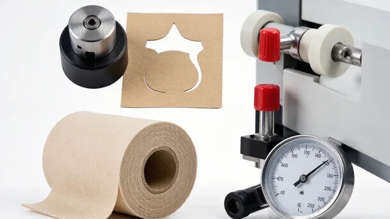
Material Properties
Material hardness, density, elasticity, compressibility, tensile strength, and dimensional stability all affect cutting behavior.
Rigid films generally maintain their shape better than soft cellular materials. However, even thin films can stretch or wrinkle when web tension is not controlled. Foam, rubber, and silicone may deform under cutting pressure and recover after processing.
Material Thickness
Thickness affects cutting force, edge condition, tool penetration, and material deformation. Thick or soft materials usually require more attention to compression and sidewall shape, while thin materials are often more sensitive to tension and handling.
The thickness tolerance of the original roll must also be considered. A cutting process cannot completely remove variation already present in the raw material.
Part Size and Geometry
Small holes, narrow borders, sharp internal corners, long thin sections, and closely spaced features are more difficult to control than simple outer profiles.
Complex geometry can also make waste removal more difficult. If the surrounding waste pulls on the finished part, the component may stretch, lift, or shift after cutting.
Tooling Condition
Tool type, blade angle, tool height, sharpness, wear, and installation all influence accuracy. A worn blade can increase cutting force, produce rough edges, or cause incomplete cutting.
Tooling selection should therefore reflect the material, thickness, production volume, and critical dimensions.
Feeding and Web Tension
In rotary die cutting and other roll-to-roll processes, web tension must remain stable throughout feeding, lamination, cutting, and waste removal.
Excessive tension can stretch films, adhesive tapes, and conductive materials. Insufficient tension may cause wrinkling, wandering, or inconsistent registration.
Environmental Conditions
Temperature and humidity can affect the dimensions and handling characteristics of foam, rubber, paper liners, adhesives, and some plastic films.
Materials should be stored and processed under controlled conditions when dimensional stability is important. Samples should also be measured under a defined and repeatable condition.
How Different Die Cut Materials Affect Tolerance?
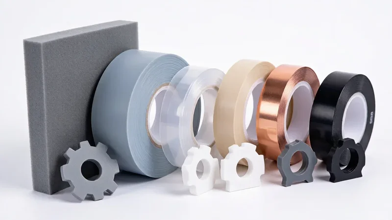
PET and PI Films
PET, polyimide, and other engineering films are commonly used for electrical insulation, surface protection, and structural separation.
These materials can support accurate profiles because they are relatively thin and dimensionally stable. However, tolerance can still be affected by:
Web tension
Material curl
Heat exposure
Static electricity
Liner stability
Hole-to-hole registration
Multi-layer lamination
For custom precision die cutting insulating films, the supplier should evaluate both the film and any adhesive, coating, or liner attached to it.
Adhesive Tapes
Die cut adhesive tape is widely used for bonding, mounting, sealing, and vibration control. The converted structure may include a carrier film, adhesive layers, release liner, and protective film.
The dimensional result depends on more than the carrier thickness. Adhesive flow, liner stiffness, storage temperature, and waste removal can all influence the finished shape.
Thicker or softer adhesive layers may also create adhesive squeeze-out at narrow edges. For precision die cut adhesive tape, the tooling and release liner must be selected to support clean cutting and stable handling.
Foam and Sponge
Custom die cut foam is used for cushioning, sealing, dust protection, insulation, and pressure management. Foam density, cell structure, compression force, and recovery behavior can significantly affect tolerance.
As a blade enters thick foam, the material may compress before it is fully cut. This can create a sidewall that is narrower in the middle than at the top and bottom. The condition is sometimes described as an apple-core or dish-shaped cut.
A foam gasket should therefore be evaluated not only by its top surface dimensions but also by its sidewall condition, thickness, and performance after compression.
Rubber and Silicone
Rubber and silicone components may stretch during cutting and recover after the cutting force is removed. Their dimensional behavior depends on hardness, thickness, formulation, temperature, and part geometry.
Small holes and narrow sections can be especially difficult because the material may deform or tear during cutting and waste removal.
The drawing should state whether the part is measured in a free state or under a defined compression condition.
Copper Foil and Conductive Materials
Die cut copper foil, aluminum foil, conductive fabric, and conductive foam are used in EMI shielding, grounding, and electrical connection applications.
Thin conductive materials can wrinkle, crease, or distort during lamination and waste removal. Burrs or damaged edges may also affect electrical contact.
For die cut conductive foam and EMI shielding gaskets, dimensional inspection may need to be combined with electrical or compression-performance testing.
Thermal and Insulation Materials
A precision die cut thermal interface material must fit the target heat source and maintain sufficient surface contact. Poor dimensional control may leave part of the heat-generating component uncovered or interfere with surrounding structures.
Thermal pads and insulating materials may also be soft, tacky, brittle, or easily compressed. Cutting depth, handling, liner selection, and packaging must therefore be considered together.
Multi-Layer Laminates
Multi-layer precision die cut parts may combine foam, adhesive tape, PET film, copper foil, conductive fabric, thermal material, insulation film, or release liners.
Each layer introduces additional potential variation. The final result can be affected by:
Individual material thickness tolerances
Lamination pressure
Adhesive flow
Layer-to-layer registration
Liner movement
Cutting sequence
Waste removal direction
Total thickness accumulation
For these products, tolerance should be assessed at the finished assembly level rather than by evaluating each layer separately.
How Material Thickness Affects Cutting Accuracy?
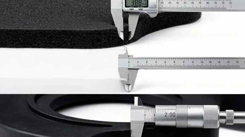
Material thickness does not affect every material in the same way.
A thin film may require low cutting force but can be sensitive to stretching and web tension. A thick foam may be less affected by tension but more likely to compress under the cutting tool. A hard insulation sheet may maintain its profile but require greater cutting pressure, which can accelerate tool wear.
Important thickness-related considerations include:
Raw Material Thickness Variation
A material roll may not have exactly the same thickness across its width or throughout its length. This variation can change kiss-cut depth, cutting pressure, compression, and liner protection.
Incoming material inspection is therefore important before precision die cutting begins.
Cutting Through Thick Soft Materials
Thick foam and rubber may compress before the blade reaches the bottom surface. Increased compression can affect sidewall shape and feature size.
Sharper tooling, appropriate blade geometry, controlled pressure, and a suitable cutting process can help reduce deformation.
Multi-Layer Thickness Accumulation
The total thickness of a laminated component is influenced by every material layer. Even when each layer remains within its own specification, the combined assembly may show greater variation.
The supplier should confirm whether the drawing specifies individual layer thickness or final laminated thickness.
Kiss Cutting and Liner Protection
In kiss cutting, the tool must cut through the functional material while keeping the release liner intact.
Variation in material or liner thickness can cause incomplete cutting or liner damage. Process pressure and tool height must therefore be matched to the complete material stack.
Common Tolerance-Related Defects
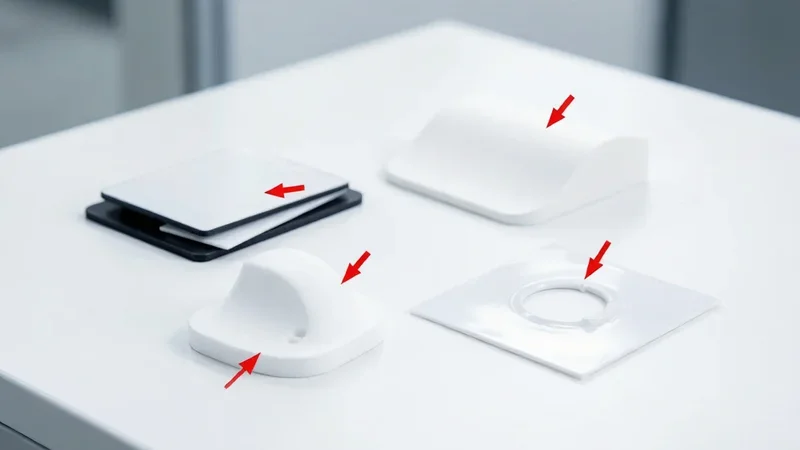
Several defects can indicate that the material, tooling, and process are not properly matched.
Compression and Rebound
Soft materials may be smaller or distorted immediately after cutting and then recover over time. A consistent measurement time should be defined when this behavior is significant.
Sidewall Deformation
Thick foam and rubber can develop curved or tapered sidewalls instead of a straight vertical edge. This may affect sealing contact or fit inside a housing.
Stretching and Shrinkage
Thin films and adhesive tapes may stretch under web tension and shrink after cutting. Long parts and narrow strips are often more sensitive to this behavior.
Layer Misregistration
In laminated parts, one layer may shift relative to another. This can expose adhesive, reduce shielding coverage, or interfere with assembly.
Adhesive Squeeze-Out
Soft pressure-sensitive adhesive may extend beyond the edge of a narrow component. It can contaminate packaging, interfere with automated placement, or create assembly problems.
Burrs and Incomplete Cuts
Foils, films, and harder materials may show burrs, rough edges, or incomplete separation when the tool is worn or cutting pressure is unsuitable.
Liner Damage
Excessive cutting depth can damage or cut through the release liner. Insufficient depth can leave the part connected to the surrounding waste.
Flatbed, Rotary and Digital Cutting Tolerances
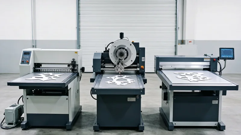
The appropriate process depends on the material, part design, production volume, and required stability.
Rotary die cutting can provide efficient, repeatable production for high-volume parts, but only when web tension and registration are controlled. Flatbed die cutting can accommodate thicker or larger materials, although soft materials may experience compression during the cutting stroke.
Digital cutting is useful for early samples and engineering evaluation. However, a digitally cut sample may not reproduce every edge condition or material behavior of the final rotary or flatbed production process. Critical projects should therefore be validated using the planned mass-production method before final approval.
How Precision Die-Cut Parts Are Inspected?
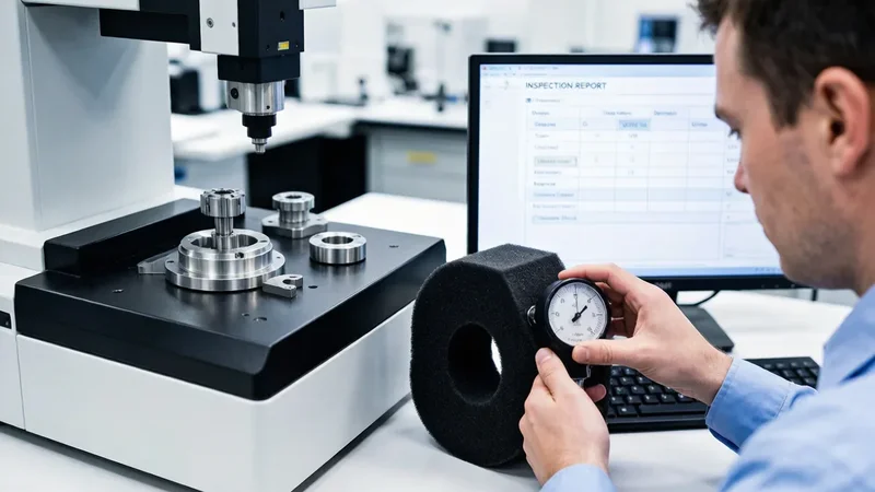
Reliable tolerance control requires inspection throughout the manufacturing process, not only after production is complete.
Incoming Material Inspection
Incoming inspection confirms material type, thickness, appearance, liner condition, and other project-specific requirements. Material batch information should be recorded when traceability is required.
First Article Inspection
The first completed parts are checked against the approved drawing before full production begins. Critical dimensions, hole positions, layer registration, cutting depth, and appearance should be reviewed.
If the first article does not meet requirements, tooling or process parameters can be adjusted before additional material is processed.
In-Process Inspection
In-process inspection helps detect changes caused by tool wear, web movement, material variation, or pressure changes.
The inspection frequency should reflect production volume, process stability, material behavior, and the importance of the measured dimension.
Optical and Vision Measurement
Optical measuring systems are useful for checking profiles, small holes, narrow borders, feature positions, and other two-dimensional dimensions without compressing the part.
Automated vision inspection can also help identify missing features, dimensional deviations, contamination, and registration problems during high-volume production.
Thickness Measurement
Thickness should be measured using a method appropriate for the material. Excessive measuring force can compress foam or thermal pads and produce an inaccurate result.
The measuring instrument, contact pressure, sample condition, and measurement location should remain consistent.
Final Inspection and Documentation
Final inspection may include dimensional checks, appearance inspection, liner condition, packaging verification, and functional testing.
Depending on the project, customers may request:
Dimensional inspection reports
First article inspection reports
Material certificates
Batch records
Process inspection data
Traceability information
Process capability data
Xinyusheng’s documented quality-control workflow includes incoming inspection, first article confirmation, in-process inspection, final quality checks, outgoing inspection, and automated CCD inspection. Its company materials also state that full inspection can be arranged for applicable products.
How to Specify Die Cutting Tolerances on a Drawing?
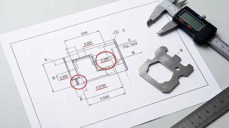
A well-prepared drawing helps the supplier select the correct material, tooling, and inspection method.
The drawing should identify:
Material type and grade
Individual and total thickness
Adhesive and liner structure
Critical dimensions
General dimensions
Datum points
Hole and slot locations
Layer registration requirements
Kiss-cut or through-cut requirements
Measurement condition
Functional and assembly requirements
Avoid applying the tightest tolerance to every dimension unless it is functionally necessary. Instead, identify the dimensions that affect sealing, positioning, bonding, electrical contact, thermal contact, or automated assembly.
It is also helpful to explain how the part fits into the final product. A dimension that appears minor on a standalone drawing may become critical when aligned with a sensor, connector, housing, or battery component.
Balancing Tolerance, Cost and Production Volume

Tighter tolerances can require more expensive tooling, lower production speeds, additional inspection, increased material usage, and more frequent process adjustments.
The lowest possible tolerance is therefore not always the best specification.
A practical tolerance should protect product function while allowing stable manufacturing. During the design review, engineers should consider:
Which dimensions directly affect function
Which dimensions only affect appearance
Whether the assembly can absorb minor variation
Whether automated placement requires tighter positioning
Whether the selected material can remain dimensionally stable
Whether inspection can reliably measure the requested tolerance
Whether the tolerance must be maintained during mass production
This functional approach can reduce unnecessary cost without compromising product performance.
RFQ Checklist for Precision Die-Cut Parts
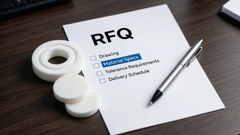
For a faster and more accurate evaluation, provide the following information with your request for quotation:
2D drawing or CAD file
Material name, grade, and supplier
Material and adhesive thickness
Complete laminated structure
Critical dimensions and tolerances
Kiss-cut or through-cut requirements
Application and assembly method
Operating temperature and environment
Inspection and reporting requirements
Prototype and annual production quantities
Packaging and delivery format
Any special cleanliness or traceability requirements
When the final material has not yet been selected, provide the functional requirements instead. A custom precision die cutting supplier can then evaluate suitable foam, film, adhesive tape, conductive, thermal, or insulation materials.
How Xinyusheng Supports Precision Die Cutting Projects?
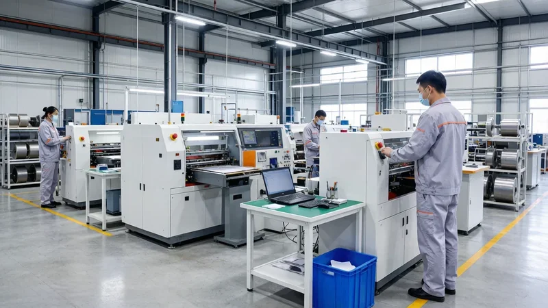
Xinyusheng provides custom precision die cutting services for functional components used in consumer electronics, automotive electronics, new energy systems, communications, medical equipment, and industrial applications.
The engineering process begins with the customer’s drawing, material requirements, and application conditions. The team can support material evaluation, structural review, sampling, inspection, and mass production using flatbed and rotary die cutting processes.
Available converting materials include adhesive tapes, foam, protective films, insulation films, copper foil, conductive fabric, thermal interface materials, mesh, and multi-layer laminated structures.
For tolerance-sensitive projects, Xinyusheng reviews the relationship between material behavior, thickness, part geometry, tooling, production method, and inspection requirements. Final achievable tolerances are confirmed through drawing review, sample production, and measurement rather than applying one tolerance value to every material or design.
The documented project workflow also includes technical communication, drawing confirmation, sampling, sample approval, mass production, inspection, packaging, and delivery.
Conclusion
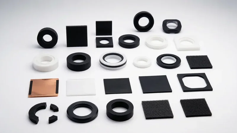
Precision die cutting tolerances depend on much more than machine positioning accuracy. Material stability, thickness, compression, part geometry, tooling, web tension, lamination, waste removal, and inspection all influence the dimensions of the finished component.
Thin films, adhesive tapes, foam, rubber, conductive materials, thermal pads, and multi-layer laminates each require a different tolerance strategy. The most reliable results come from identifying critical dimensions, reviewing the complete material structure, validating samples, and maintaining inspection throughout production.
For a project evaluation, send Xinyusheng your drawing, material specifications, tolerance requirements, application conditions, and expected production volume. Our engineering team will review the design and recommend a practical precision die cutting solution for sampling and mass production.
Table of Contents
Related news
Company News
What Is Custom Precision Die Cutting? What Types of Custom Functional Components Is Xinyusheng Suitable For?
May 14,2026
Discover More
Company News
How Are Die Cut Materials Used in Automotive Electronics?
August 29,2026
Discover More
Company News
What Types of Thermal Interface Materials Can Be Die Cut?
August 29,2026
Discover More
