How to Specify Precision Die-Cut Parts and Avoid Costly Rework
A die-cut gasket or adhesive frame can look simple on a drawing. Yet a few missing notes can force a converter to guess how the material should behave, which dimensions control function, and how the part will be handled on the assembly line. Those guesses often become late samples, revised tooling, rejected lots, or a component that meets the print but fails in use.
A useful specification does more than define an outline. It connects geometry with material construction, manufacturing method, inspection, and the final assembly. The aim is not to create the longest drawing possible. It is to remove ambiguity where ambiguity creates risk. For more engineering guidance, explore our precision die cutting resources.
Start a Custom Precision Die Cutting Specification with Function
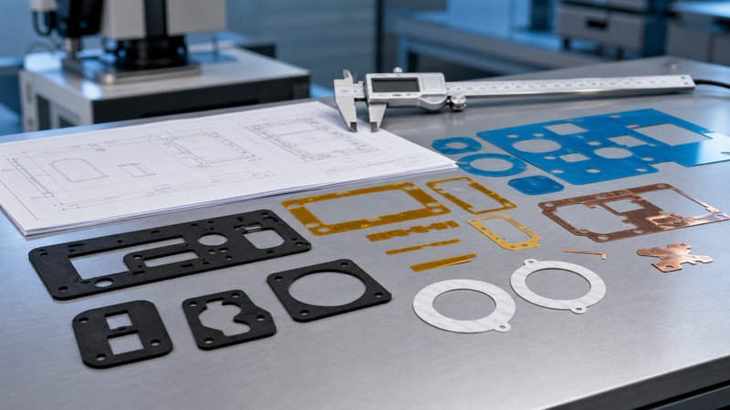
Before assigning tolerances, describe what the part must do. A foam ring may seal dust, compensate for a housing gap, and keep a sensor centered. An insulation film may prevent electrical contact while leaving connector and screw areas open. An adhesive frame may bond a display and also define the visible border.
These functions identify the critical features. If seal width controls the IP performance, it deserves a specific tolerance. If two holes locate the part during automatic placement, their true relationship matters more than a decorative outside edge. Functional context also helps the converter challenge a design that is difficult to manufacture but easy to improve.
Translate each function into a verifiable requirement before drawing release. A sealing feature needs a target compression range and the mating gap; an adhesive frame needs substrate, surface energy, bond area, dwell time, and environmental exposure; an insulation part needs operating voltage, creepage clearance, temperature class, and flame requirement. This function-to-requirement chain prevents a drawing from controlling geometry while leaving the actual performance undefined.
Define Materials for Precision Die Cut Component Parts

Descriptions such as “black foam,” “double-sided tape,” or “PET film” are not manufacturing specifications. The same material family can include very different thicknesses, densities, adhesive chemistries, surface treatments, release liners, temperature ratings, and compression behavior.
A complete callout should identify the manufacturer and grade when these are fixed. It should also state nominal thickness, color, density or hardness where relevant, adhesive type, liner construction, and required performance. If an approved equivalent is acceptable, define the properties that must remain equivalent rather than allowing an uncontrolled substitution. Review our die-cut tape materials, foam materials, and insulation materials when building the callout.
For a multilayer part, show the stack in order. An exploded section can clarify which side carries adhesive, where the liner must remain, and whether selected zones should be free of adhesive. The total thickness alone cannot communicate this structure.
Material tolerances should also be considered at stack level. Three individually acceptable layers can produce an unacceptable total thickness when their upper limits accumulate. Define whether thickness is measured before lamination, after lamination, or under a specified pressure, and record grain or machine direction when dimensional stability or peel behavior depends on it.
Apply Precision Die Cutting Tolerances Selectively
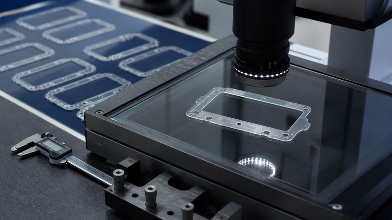
Putting the tightest tolerance on every dimension rarely produces a better component. It increases tooling and inspection cost and may create unnecessary rejections. Flexible materials also behave differently from machined metal: foam compresses, rubber recovers, adhesive flows, and liners stretch.
Classify dimensions as critical, important, or reference. Critical dimensions affect fit, sealing, thermal contact, electrical isolation, or automatic placement. Important dimensions support handling or appearance. Reference dimensions help interpretation but should not create additional acceptance criteria.
Use a consistent datum system. Avoid long chains in which the tolerance of one feature depends on several preceding dimensions. Where two holes must align with locating pins, dimension them from the same datum and define their positional relationship directly.
Tolerance should also be tied to a measurement method. A hole position measured from a stable locating edge is more reproducible than the same position inferred from two flexible outer edges. For multilayer parts, separate profile tolerance from layer-to-layer registration; they are different error sources and may require different inspection setups.
Xinyusheng’s process envelope includes precision up to ±0.03 mm and features down to approximately Ø0.5 mm when the material and geometry are suitable. Foam recovery, adhesive flow, liner stiffness, part size, tool wear, and the agreed measurement condition still determine what is defensible on a specific drawing.
Do not treat a capability figure as a universal drawing tolerance. A useful tolerance review compares the required limit with short-term process variation, measurement uncertainty, and material movement after conditioning. Where capability data is required, specify the characteristic, sampling window, and target index; otherwise two suppliers can report “capable” results from different methods that are not comparable.
Specify Full Cut, Kiss Cut, and Liner Requirements
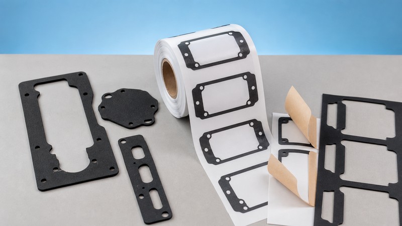
“Die cut” does not tell a supplier how deeply to cut. A full cut passes through the complete construction. A kiss cut separates the functional material and adhesive while keeping the release liner intact. Some parts require multiple cutting levels, split liners, finger lifts, or selective adhesive removal.
State what must be cut, what must remain, and how the liner should behave when peeled. If liner damage is unacceptable, define a practical acceptance criterion. If parts will be supplied on a roll, include unwind direction, part orientation, spacing, maximum roll diameter, core size, and splice rules.
Assembly method matters here. A hand-applied part may need a generous pull tab. Automated dispensing may require stable liner release, consistent pitch, a defined leading edge, and sufficient stiffness for reliable pickup.
For kiss-cut parts, define liner acceptance in functional terms: the part must remove cleanly without liner fiber lift, adhesive transfer, or breakthrough that causes web tearing. A retained liner is not automatically acceptable if knife impressions weaken it. Trial the actual peel angle and dispensing speed because a liner that works during hand inspection may fail in automated feeding.
Make Manufacturing Precision Die Cut Component Parts Inspectable
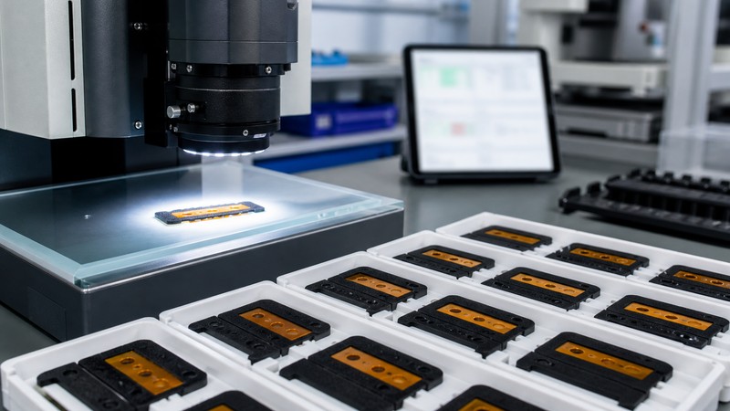
A specification should explain how acceptance will be determined. Identify the dimensions included in the first-article report and the measurement method expected for profiles, holes, thickness, or layer registration. Visual requirements should cover problems that dimensional inspection may miss, such as adhesive ooze, delamination, contamination, edge tearing, incomplete waste removal, or distorted foam.
Do not demand an inspection method that damages the part unless destructive sampling is intentional. For very soft components, agree on measurement pressure and conditioning time because caliper force can change the result. For critical programs, clarify sampling level, lot traceability, material certificates, and whether capability data is required.
The inspection plan should separate setup approval from routine production control. First-article inspection confirms tool geometry and layer registration; in-process checks monitor drift from tool wear, adhesive buildup, web tension, and temperature. For optical measurements, define edge-detection rules and datum alignment. For thickness or compression, define probe area, force, dwell time, and conditioning so results can be reproduced by both customer and supplier.
Review the Precision Die-Cutting Package Before Tooling
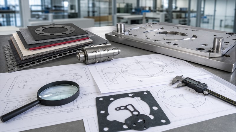
The best time to find a specification problem is before a production tool is ordered. Conduct a joint review of the drawing, material stack, application, volume, delivery format, and inspection plan. Ask the converter to identify narrow waste areas, unstable features, excessive tolerance demands, and conflicts between the liner design and application method.
For complex components, review material selection, lamination, sampling, inspection, and packaging as one manufacturing route. This is especially useful when the part combines electrical, thermal, insulating, sealing, or skin-contact functions.
Close the review with a controlled list of open items and ownership. Confirm drawing revision, approved material sources, tool type, expected tool life, sample quantity, measurement report, delivery format, labeling, and change-control route. Tooling should begin only when assumptions that could alter cut geometry, liner design, or process selection have been resolved.
FAQ About Precision Die Cut Specifications
Can a physical sample replace a drawing?
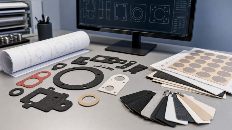
A sample can start the discussion, but it does not define nominal dimensions, acceptable variation, material grade, or critical features. A controlled drawing should be created before production approval.
Should I specify a brand-name adhesive?
Specify it when qualification, regulatory documentation, or prior testing depends on that product. If alternatives are acceptable, define adhesion, temperature, thickness, substrate compatibility, and aging requirements.
What file formats are most useful?
PDF is useful for controlled dimensions and notes. DXF or DWG supports accurate 2D geometry. A STEP model can provide assembly context, but the controlled acceptance dimensions should still be clear.
Who should approve a material change?
The drawing or quality agreement should identify the approval authority. Functional materials should not be substituted solely because they look or feel similar.
Send Us Your Precision Die-Cutting Specification
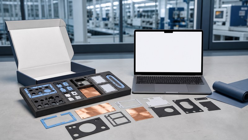
Share your drawing, material stack, application, expected volume, and delivery format with Xinyusheng. Our engineering team can review manufacturability, identify missing requirements, and develop a sampling plan before tooling and mass production.
For a faster technical review, include the controlled PDF, editable 2D geometry, annual and release quantities, critical-to-function dimensions, approved material list, assembly method, and inspection expectations. If any item is still undecided, mark it clearly so the sampling plan can test the risk rather than silently fixing an assumption into production tooling.
Table of Contents
Related news
Company News
What Is Custom Precision Die Cutting? What Types of Custom Functional Components Is Xinyusheng Suitable For?
May 14,2026
Discover More

Company News
How Are Die Cut Materials Used in Automotive Electronics?
August 29,2026
Discover More
Company News
What Types of Thermal Interface Materials Can Be Die Cut?
August 29,2026
Discover More
